© ArduTV 2025
Nano Raspberry RP2040 - Audio meter

In this simple simple example we use the Arduino Raspberry nano RP2040 to show an audio meter on the television (using the microphone of the nano board). IMPORTANT: The 3.3V/5V switch mode of the ArduTV is set to 3.3V.
NOTE: The example is a modification of the standard Arduino example.
The code of the Example
/*
This ArduTV example projects and it is based on the standard Arduino example.
This example reads audio data from the on-board PDM microphones, and prints
out the samples to the Serial console. The Serial Plotter built into the
Arduino IDE can be used to plot the audio data (Tools -> Serial Plotter)
Circuit:
- Arduino Nano 33 BLE board, or
- Arduino Nano RP2040 Connect, or
- Arduino Portenta H7 board plus Portenta Vision Shield, or
- Arduino Nicla Vision
This example code is in the public domain.
*/
#include
#include
ArduTV HDMI1(10);
// default number of output channels
static const char channels = 1;
// default PCM output frequency
static const int frequency = 10000;
// Buffer to read samples into, each sample is 16-bits
short sampleBuffer[512];
//unsigned short sampleBuffer[512];
// Number of audio samples read
volatile int samplesRead;
volatile u16 ToPrint,ascissa;
volatile int last;
void setup() {
Serial.begin(9600);
// while (!Serial);
// Configure the data receive callback
PDM.onReceive(onPDMdata);
// Optionally set the gain
// Defaults to 20 on the BLE Sense and 24 on the Portenta Vision Shield
PDM.setGain(-20);
// Initialize PDM with:
// - one channel (mono mode)
// - a 16 kHz sample rate for the Arduino Nano 33 BLE Sense
// - a 32 kHz or 64 kHz sample rate for the Arduino Portenta Vision Shield
if (!PDM.begin(channels, frequency)) {
Serial.println("Failed to start PDM!");
while (1);
}
HDMI1.begin();
HDMI1.BGColor(31,31,31);
HDMI1.PenColor(0,0,20);
HDMI1.Clear();
HDMI1.Rect(0, 195, 610, 58, 0);
HDMI1.Rect(1, 196, 611, 58, 0);
HDMI1.PenColor(0, 0, 20);
HDMI1.printString("ARDUTV with Nano RP2040", 150, 15, 2);
HDMI1.printString("Microphone TEST", 170, 80, 2);
HDMI1.PenColor(31, 0, 0);
HDMI1.printString("Audio level meter", 80, 170, 1);
}
void loop() {
// for (int i = 0; i < 400; i++){
//HDMI1.PenColor(31,31,31);
//HDMI1.Rect(0, 200,600,20,1);
//}
// Wait for samples to be read
if (samplesRead) {
//Serial.print("N=");
// Serial.println(samplesRead);
// Print samples to the serial monitor or plotter
int CampMax=0;
for (int i = 0; i < samplesRead; i++) {
CampMax=max(CampMax,abs(sampleBuffer[i]));
}
int t=(int) ((CampMax/32768.0f)*30); //num of pixel
if (t>last) {
last=last+1;
int x= (int)((31.0/30)*last);
HDMI1.PenColor(31-x,x,20);
//HDMI1.Point(100, i);
HDMI1.Rect(0+(last*20), 200, 20, 50,1);
}else if (t==last){
}else if (t
{
int x= (int)((31.0/30)*last);
HDMI1.PenColor(31,31,31);
//HDMI1.Point(100, i);
HDMI1.Rect(0+(last*20), 200, 20, 50,1);
last=last-1;
}
// Clear the read count
samplesRead = 0;
}
// Serial.println("Ale");
delay(10);
//delay(500);
}
/**
* Callback function to process the data from the PDM microphone.
* NOTE: This callback is executed as part of an ISR.
* Therefore using `Serial` to print messages inside this function isn't supported.
* */
void onPDMdata() {
// Query the number of available bytes
int bytesAvailable = PDM.available();
// Read into the sample buffer
PDM.read(sampleBuffer, bytesAvailable);
// 16-bit, 2 bytes per sample
samplesRead = bytesAvailable / 2;
}
Project Pictures


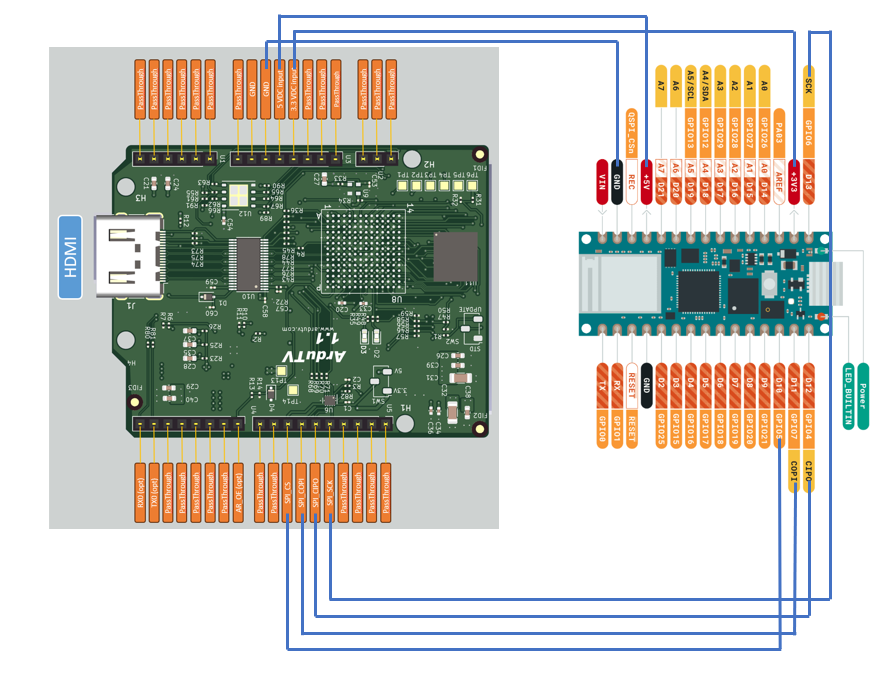
Connection Diagram
Example Setup
NOTE: On nano board the 5V output must be enabled (the pads on the bottom must be shorted).
In the example one breackout board shield is used to connect nano Board.
Watch the video of the example project
Audio Meter
© ArduTV 2025